REXCPM Installation in T102: Difference between revisions
(Created page with "work in progress! Stay tuned The hardware you need is shown here. (You also need a 3 wire cable assembly, provided with the adapter.)") |
No edit summary |
||
| (6 intermediate revisions by the same user not shown) | |||
| Line 1: | Line 1: | ||
The | |||
The main difference between installation in M100 and T102 is that the T102 system bus, being at the back of the computer, is hard to use. So, there's no way to have a little PCB to create the "RAM" signal based on pins that can be accessed. | |||
Luckily, the T102 main board has a signal that is usable for "RAM" indicator. The challenge is that you have to solder a wire onto a specific surface mount IC pin to get at it. | |||
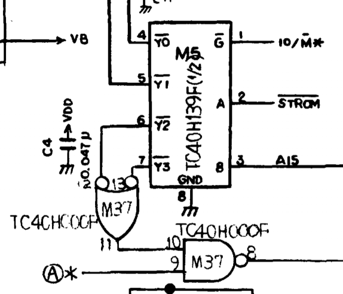
The IC that you need to solder to is M37, as shown in this snip from the T102 schematic. The signal of interest can be found at pin 10 and 11 on M37. This signal goes "high" when the upper addresses 08000-0FFFF hex are being accessed. | |||
[[Image:ckt_T102_REXCPM_1.PNG]] | |||
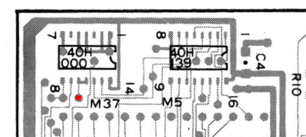
M37 is found on the secondary side, more or less underneath the OPTION ROM socket. | |||
Here is a snip of the PCB area. Pin 11/10 can be seen as shorted together. The signal location is indicated with the red dot. | |||
[[Image:layout_T102_REXCPM.PNG]] | |||
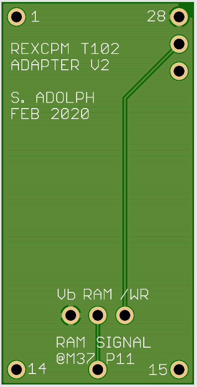
So the key step is to solder a wire at this location, and connect to the spot indicated on the T102 REXCPM adapter. I think it may be easiest, since 10 and 11 are connected on the board, to solder the wire BETWEEN those pins. The T102 adapter is shown below, and the location to solder the wire is clearly marked. | |||
[[Image:T102_adapter_REXCPM.PNG]] | |||
Installation steps: | |||
1) Disassemble your T102, and remove the PCB. | |||
2) Locate M37; solder an appropriate small gauge wire of a suitable length (4 inches?) to Pin 11/10 of M37. | |||
3) Solder the other end of the wire to the T102 adapter at the necessary location. | |||
4) Insert the T102 adapter into the socket for M6 | |||
- This is the "upgrade RAM" socket immediately next to the OPTION ROM socket. | |||
- Remove the upgrade RAM chip if it is installed. | |||
- ensure pin 1 of the adapter is pin 1 of the socket. | |||
5) Reassemble your T102. | |||
6) Insert REXCPM into OPTION ROM socket, and connect the 3 wire jumper from REXCPM to the T102 Adapter. | |||
- Ensure orientation of the jumper wires is correct. | |||
- The color sequence should be the same on both REXCPM and T102 Adapter. | |||
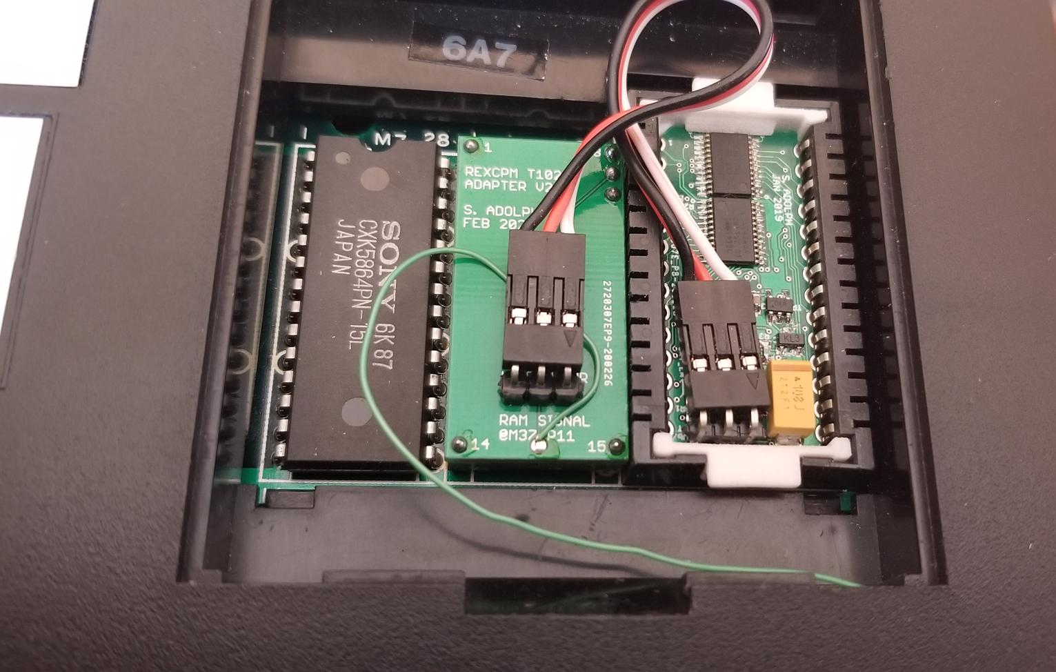
Here is a photo of a finished installation: | |||
[[Image:T102_REXCPM_installed.jpg]] | |||
Latest revision as of 10:13, 1 March 2021
The main difference between installation in M100 and T102 is that the T102 system bus, being at the back of the computer, is hard to use. So, there's no way to have a little PCB to create the "RAM" signal based on pins that can be accessed.
Luckily, the T102 main board has a signal that is usable for "RAM" indicator. The challenge is that you have to solder a wire onto a specific surface mount IC pin to get at it.
The IC that you need to solder to is M37, as shown in this snip from the T102 schematic. The signal of interest can be found at pin 10 and 11 on M37. This signal goes "high" when the upper addresses 08000-0FFFF hex are being accessed.
M37 is found on the secondary side, more or less underneath the OPTION ROM socket.
Here is a snip of the PCB area. Pin 11/10 can be seen as shorted together. The signal location is indicated with the red dot.
So the key step is to solder a wire at this location, and connect to the spot indicated on the T102 REXCPM adapter. I think it may be easiest, since 10 and 11 are connected on the board, to solder the wire BETWEEN those pins. The T102 adapter is shown below, and the location to solder the wire is clearly marked.
Installation steps:
  1) Disassemble your T102, and remove the PCB.
  2) Locate M37; solder an appropriate small gauge wire of a suitable length (4 inches?) to Pin 11/10 of M37.
  3) Solder the other end of the wire to the T102 adapter at the necessary location.
  4) Insert the T102 adapter into the socket for M6
     - This is the "upgrade RAM" socket immediately next to the OPTION ROM socket.
     - Remove the upgrade RAM chip if it is installed.
     - ensure pin 1 of the adapter is pin 1 of the socket.
  5) Reassemble your T102.
  6) Insert REXCPM into OPTION ROM socket, and connect the 3 wire jumper from REXCPM to the T102 Adapter.
     - Ensure orientation of the jumper wires is correct.
     - The color sequence should be the same on both REXCPM and T102 Adapter.
Here is a photo of a finished installation:


